|
|
|||||||||
Stability
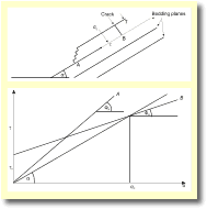
Planar slides of weak rock which overlies competent or stratified rock with bedding parallel to the slope can be modelled quite simply. The normal stress acting on a unit area of the slip surface between the two rock material is a combination of the normal stress (sn) and shearing stress (t) (Fig. 3). The magnitudes of these factors will depend on the thickness (T) of the slab. For the driving forces to equal the resisting forces, i.e. safety factor N = 1 (Costa and Baker 1981): where tn is the initial shear resistance of the slip surface and tan F is the characteristic angle of internal friction of the material. Both these factors would have be estimated or established using engineering tests. If the slab has a lower angle of internal resistance, but some initial shear resistance, the failure line, B, will intersect the shearing stress line at a particular critical normal stress, sc, (provided that FB < a.). This critical stress is produced by that precise thickness of slab material that, if exceeded, will create shearing stress along the failure surface. To maintain a stable slope in this case requires that the slab must be thinner than this critical value. In relatively homogeneous material with no internal bedding of
lineations the failure plane will often assume a circular shape
and will form a slump. Such a failure can be expected when the thickness
of the material likely to fail is greater than the height of the
slope. The failure plane will be some unknown slip surface, usually
curved, along which resisting forces : driving forces is
minimum. Method of moments
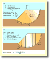
The acting moment of the driving forces is a product of the total weight of the potential slump and x. The safety factor is calculated as follows:
Failure may not occur on the plane identified in Figure 4 and trial
and error will identify the arc which has the lowest safety factor,
and this arc is the one that should be used in design as it is the
arc along which failure is most likely. Method of slices In the method of slices the slope is divided into vertical slices and the stability of each slice evaluated (Fig. 4). The safety factor is calculated as:
Where S is the normal component of slice weight, T is the tangential component of slice weight, F is the friction angle for each slice (determined by laboratory tests and Ts is the cohesion along the arc (also determined by laboratory tests). As in the method of moments calculation a number of different calculations will need to be made to identify the arc surface which is most likely to fail. These calculations are often made using a computer.
|
|||||||||
|
|||||||||


